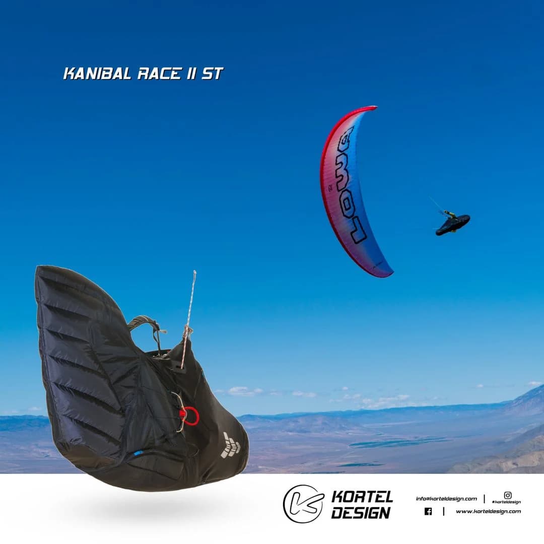
🪂 How a paraglider wing is built
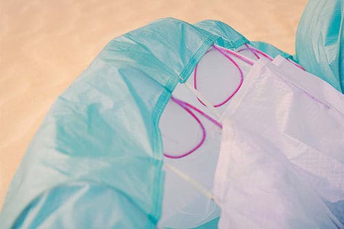
🔹 The wing of the paraglider has a close to ellipse shape when seen from above and has left and right semi-wings (directions are always chosen in relation to the flight direction). The wing consists of cells, divided by walls. 🔹 The front of the wing is called the leading edge, and this is where the cell openings are located. This is where the airflow enters and inflates the wing with air. The back part of the wing is called the trailing edge. The outermost area of each semi-wing is called an ear, which ends with a wing tip. The distance between wing tips is called wing span. 🔹 The inflated wing has an arc shape when seen from both the front and behind. There is a difference between the projected wing span of an inflated wing and the wing span of a wing spread on the ground. There is also a difference between the projected surface and the actual surface of a wing. The projected surface area is the one that carries the load, no matter how large the flat surface area on the ground is.
🔹 Each semi-wing consists of a set of profiles, formed by the shape of the cell walls. The profile has an upper and bottom surface. The distance between the front and back part of each profile is called a chord. The main characteristics of a profile are chord length, maximal profile thickness, and its position.
🧵 The line system
⚙️ The paraglider suspension: ▶ Distributes the weight of the pilot along the wing surface; ▶ Gives shape to the wing; ▶ Sets the balanced angles of attack at different wing sections (central section, ears) by changing the line length construction; ▶ Provides in-flight angle of attack control. ⚙️ The suspension consists of lines, risers, and carabiners. The lines are attached to numerous attachment points at the connection of cell walls with the bottom surface of the wing. ⚙️ As lines create drag, constructors strive to reduce their overall length—for example, using diagonals between cells improves load distribution and reduces the number of attachment points. ⚙️ Laterally (if seen from behind), the lines are divided into left and right, according to which semi-wing they are connected to. The wing tip is connected to a stabilo line, which is often a different color and is pulled to clear canopy and line cravats. ⚙️ Longitudinally (if seen from the side), the lines are divided into A, B, C, and D lines. The A lines are closest to the leading edge and the D lines are the furthest. The closest to the trailing edge are the brake lines (control lines). ⚙️ The lines leading directly from the wing surface are grouped together into thicker lines, making up the main A, B, C, D lines. Finally, they are connected to the corresponding A, B, C, and D risers through triangular metal elements called maillons. The risers are stitched together in a loop where the carabiner connects them to the pilot’s harness. ⚙️ There is a short riser with a pulley connected to the last riser. The brake line goes through it and connects to the brake handle (control handle). This ensures the controls remain within reach if accidentally released.
⚙️ Some modern and high-performance paragliders have rigid elements and may not have C or D lines/risers. ⚙️ The risers are designed so that pulling a pulley system on the A riser pulls the A, B, C, and D risers downward consecutively, reducing the angle of attack. This is called a speed system. Some paragliders have trimmers, which adjust the last risers to control the angle of attack.
💺 The harness
💺 The harness envelops the pilot's body and transfers their weight to the wing through the carabiners, risers and lines. The harness should: ▶ Hold the pilot's body in all positions (even upside down); ▶ Allow control by shifting weight sideways; ▶ Allow mounting and easy use of a speed system; ▶ Have active safety devices (reserve parachute) and passive safety devices (back protector); ▶ Allow a comfortable position lasting for hours; ▶ Allow enough freedom of movement (running on takeoff/landing, easy entry/exit). 💺 Usually, the harness has a rigid seat board for the pilot to sit on. Below it runs the main load-bearing webbing, with the carabiner loops stitched into it. Additional straps run from the harness to the carabiners to support the pilot's shoulders and back. The pilot is secured in the harness by buckling the chest strap between the carabiners and the leg straps. ⚠️ Leg strap locking is vital, as there are still lethal cases of pilots slipping out of the harness. In most modern harnesses the chest strap is linked to the leg straps by an extra strap (a "T-lock") so the pilot cannot slip out even if they forget to buckle the leg straps. Some manufacturers also use a combined chest–leg strap system (an "H-lock").
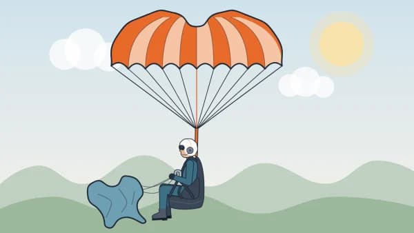
💺 Beginner harnesses are usually upright "sitting" harnesses, while experienced pilots try to reduce body drag and use pod harnesses with a streamlined leg cover. 💺 To avoid numb legs from pressing on the front of the seat after hours of flying, some harnesses can be fitted with a footrest (stirrup). It also gives better control of body position and makes it easier to get into and out of the harness at launch and landing. An elastic cord usually links the footrest to the speed bar so the pilot can find it easily with their feet. Never use the speed bar as a footrest. 🛡️ Except for some special harnesses (ultralight for hike-and-fly, acro…), harnesses are fitted with a back protector that protects the pelvis and spine from serious injury. 🛡️ A foam back protector is a moulded foam block that must meet the industry thickness standard. It sits in its own compartment so it always stays in place, absorbing and spreading the energy of an impact. Airbag systems work on the same principle: the lower part fills with air in flight, and a one-way valve at the inlet keeps the air in to form a cushion in an impact. 🚀 Manufacturers decide where to put the reserve container – under the seat, at the back, or in a separate pouch on the chest strap or at the side (front container, side container). The reserve handle must be convenient, easy to reach and easy to throw. The container and the whole reserve system must be neither too tight (hard to pull out) nor too loose (falling out and opening by accident). The reserve bridle is attached to the harness behind the pilot's shoulders via extra straps, so under the reserve the pilot's body tilts slightly forward to absorb the landing impact better.
⏳ How long the materials last
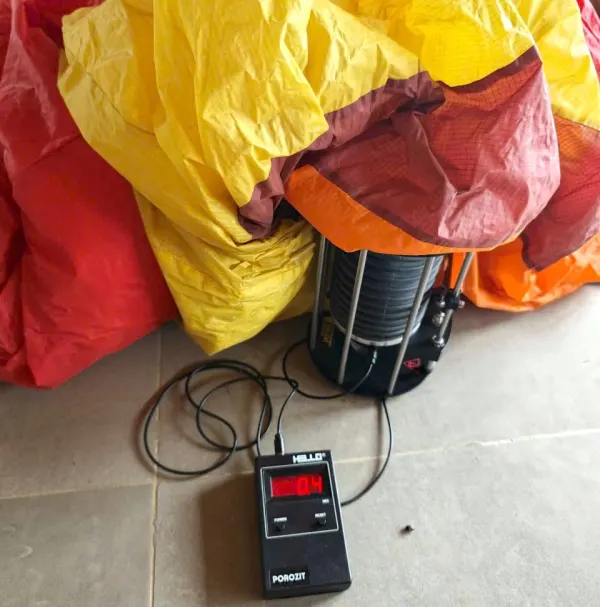
💪 To overcome their fear, new pilots need to trust the wing they are strapped to. 🧵 The wing is made of rip-stop reinforced synthetic fabric (e.g. Skytex, Gelvenor). Manufacturers choose different fabric weights (g/m²) and properties for different parts of the wing (upper and lower surface, ribs, leading edge). The fabric is machine-woven, dyed and coated under strict quality control. ☀️ A special coating protects the fabric from UV rays and reduces porosity. Fabric quality decreases over time depending on how much the wing is used, sun exposure and mechanical friction. A wing’s lifespan is typically around 300–500 flying hours, depending on the wing. Towards the end of its life porosity rises sharply and the fibres age quickly. The fabric's condition is monitored by logging flying hours and testing with a porosity meter and a fabric strength tester (bettsometer). 🧵 Depending on the suspension design, manufacturers use lines of different thickness. The most common materials are Kevlar, Dyneema, Aramid and Polyester. A 0.8 mm line can hold 80 kg; a 2.2 mm line can hold 220 kg. Unsheathed "competition" lines are more sensitive to UV and moisture and should be replaced every 150–200 hours. Other lines usually outlast the fabric unless damaged. 🧵 In normal use, lines change length because of outside influences and must be checked periodically. Moisture and temperature often shrink lines by 2–5 cm, especially the less-loaded C and D lines, changing the profile camber and the angle of attack. Such deviations are hard to notice on beginner wings but can seriously change the flying behaviour of high-performance wings with thin, sensitive profiles. ⛓️ Maillons (triangular steel links) connect lines to risers. They are threaded so they can be opened to change lines. A 3 mm stainless steel maillon holds 800 kg lengthwise and 160 kg sideways. Risers are polyester straps holding over 1100 kg. The pilot's weight is carried mainly by the left and right A and B risers. 🏗️ Measurements show that a 25 m² wing carrying a 75 kg pilot has 16 kg on each A riser and 10 kg on each B riser. Tests require wings and harnesses to withstand 10G (10 times the pilot's weight) without failure of the structure or any part (broken lines, seams, fabric, risers, carabiners…).
🧼 Caring for your wing
✨ Taking good care of your wing prolongs its life and keeps it safe and comfortable. The main causes of material ageing are environmental and mechanical. 🌍 Environmental Influences: ▶ UV sunlight, atmospheric moisture, and temperature changes. ⚙️ Mechanical Influences: ▶ Normal and extreme flight loads; ▶ Friction with the ground during launch, landing, packing and laying out; ▶ Deformation and friction during packing and transport; ▶ Snagging on branches, thorny bushes, roots, rocks… and stepping on the fabric and lines can cause tears and damage. ✈️ In aviation, good care is a must: ▶ Avoid unnecessary sun exposure: the wing, lines, risers and harness are all damaged by UV. Petroleum-based synthetic materials age quickly in the sun. ▶ Avoid moisture: If the wing gets wet, dry it completely before storing. Moisture drives dirt deep into the fabric, speeds up wear and causes line shrinkage or mould. Saltwater should be rinsed off with fresh water immediately. ▶ Avoid extreme temperatures: Heat in a car can deform plastic reinforcements. Cold combined with moisture breaks micro-fibres when the water freezes. ▶ Avoid unnecessary friction: Even dry grass acts like sandpaper on the fabric. ▶ Clean the wing: Periodically remove sand, dust and objects from the cells via the wing-tip velcro openings. ▶ Remove insects: Grasshoppers can bite holes in the fabric to get free. 🤝 Be gentle with your glider: ▶ Do not step on the fabric or lines, especially on hard, rocky ground. ▶ When pulling the wing up, check that it does not snag on rocks, roots or bushes. Be ready to stop if you feel it catch. ▶ Do not let the wing "crash" on its leading edge after landing; the pneumatic shock can burst internal cell walls. ▶ Fold cell-by-cell: Keep the rigid reinforcements parallel, don't bend them too much, and vary the way you fold to avoid permanent creases. ▶ Store in a dry, dark place at moderate temperature. ▶ Have the wing checked periodically at a professional service centre.
🔧 Repairs
🛠️ The most common damage is: ▶ Torn fabric (large rips >10 cm or small <10 cm); ▶ Damaged line sheathing; ▶ Broken lines; ▶ Loose or broken stitching. 🩹 Small rips (<10 cm) can be repaired with rip-stop adhesive tape. Cut the patch with rounded corners to prevent peeling. Clean the area around the rip, let it dry and press the patch on firmly. Rips of 2–10 cm should be patched on both sides.
⚠️ The most dangerous rips are on the top surface near the leading edge, where the highest aerodynamic loads occur. 🧵 Broken lines must be replaced with identical lines from the manufacturer – never tie a broken line together. Knots reduce line strength by up to 40% and shorten the line, which compromises safety and wing profile. 🔧 Frayed main straps and deformed hardware (maillons, carabiners, pulleys) must be replaced completely. 🪂 By Nikolay Yotov and Ivelin Kalushkov